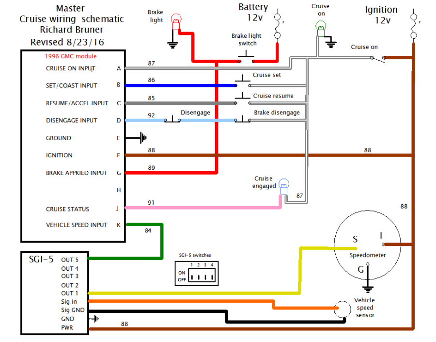
This is my cruise control using a GM control module #25169208 . GM trucks about 1995-2000. I modified the original wiring diagram to incorporate the Universal Speedometer Signal Interface (SGI-5) from Dakota Digital. I am using it to both correct my inaccurate speedometer and send a signal tothe cruise control.

Click on wiring images to get the full size PDF file
Dakota Digital Universal Speedometer Signal Interface
Click Here
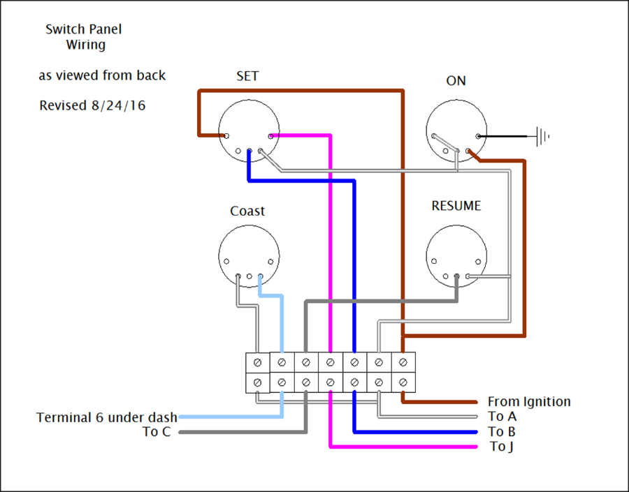


These diagrams are how I did my wiring using the switches in the picture that have their own built in light.
Note on SGI-5: This is “Application #2” on the Dakota Digital instruction sheet. I used the speed signal from the speed sensor on the transmission. I originally used output #3 but cruise would not engage below 55 MPH, I changed to output #5 and it now works above about 30 MPH.
Brake light–already on vehicle
Cruise set–normally open momentary contact
Cruise resume–normally open momentary contact
Cruise set–normally open momentary contact
Brake pedal–normally closed
Clutch pedal if used–normally closed
Disengage–normally closed
I used a normally open switch held closed for my brake pedal switch. The switch marked “Coast” on my control panel is a disengage switch. Brake,clutch and disengage are wired in series.
When cruise is engaged, “Set” button reduces set speed and “Resume” button increases speed.
I got these plans from a friend, and various web sources. It is my understanding but, not verified, that other GM cruise modules will not work. Some have hacked and mounted the original GM turn signal lever, not all are wired with normally open switches and required relays to make them work. I like my dash mounted controls with the pretty lights.
My bus is rear engine which is why I attached the cable to the accelerator pedal. I was told the module isn’t strong enough to pull against the governor if mounted on the engine.
It has occurred to me that you could make a steering wheel mounted button control using a 4 relay RC module.